Warner Electric Actuator Wiring Diagram

Rh 0405 Way Switch Wiring Diagram On Electric Linear Actuator Wiring Diagram Schematic Wiring
3bfad4 Electric Linear Actuator Wiring Diagram Wiring Library

Thomson Linear K2p1 0g10 12v Br 12 Actuator B Track 12 Vdc 600 Lbf Connector Special Mrosupply Com

How To Wire A Rocker Switch To Linear Actuator

Solved Need Wiring Diagram For The Borg Warner 4405 Control Trac Fixya
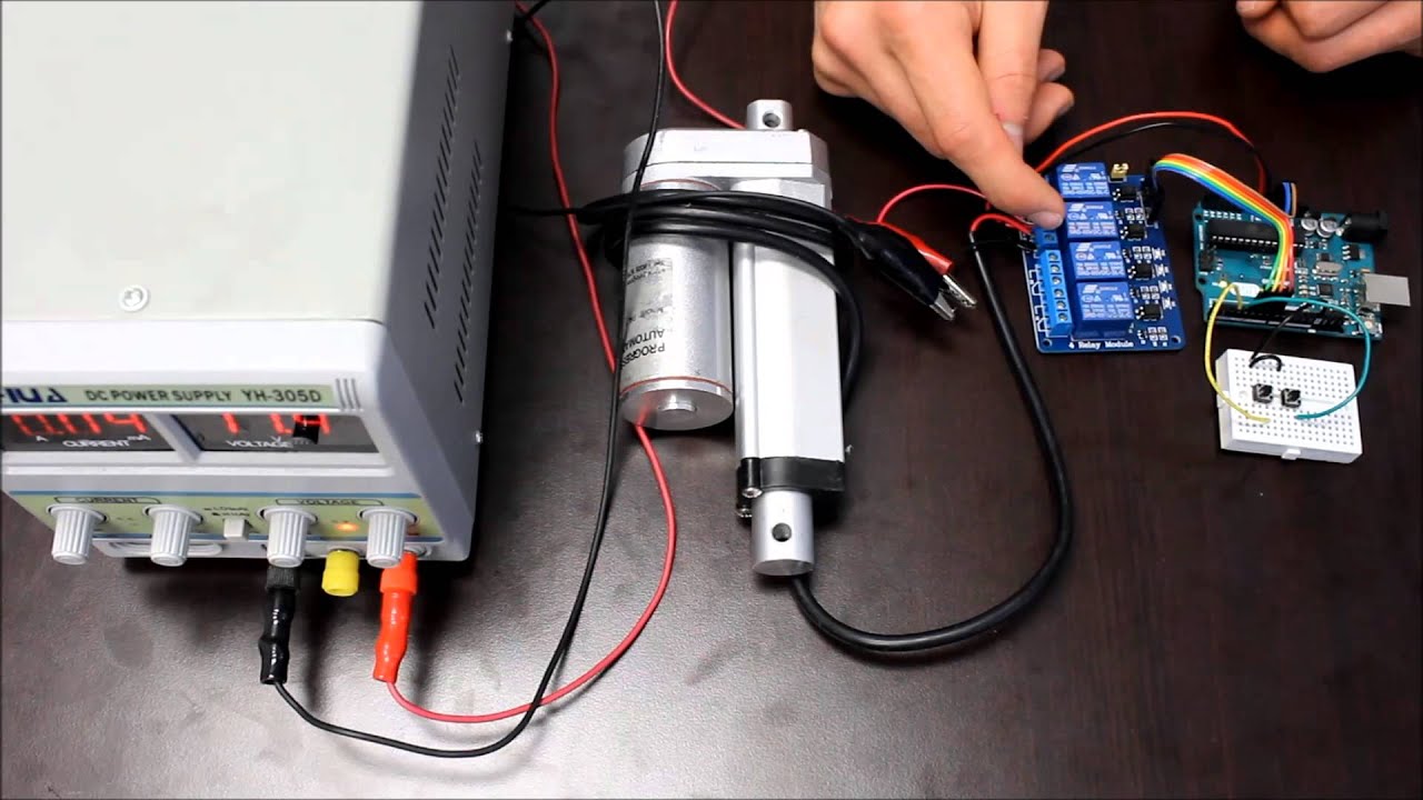
How To Use Relays To Control Linear Actuators Youtube
Collection of linear actuator wiring diagram.
Warner electric actuator wiring diagram. Warner electric parts offers products from the leading manufacturer and supplier of industrial power transmission products that includes clutches and brakes. Warner linear electric actuators and controls. 580a332 electric linear actuator wiring diagram library ms 0983 12v abz free pneumatic and actuators valve automation limitorque l120 collection warner c10594 color code control base website umldiagramtypes magentaproduction fr for controls pqs manualzz fff54. Warner electric engineers utilize the latest materials and manufacturing technologies to design long life easy to use clutches and brakes that provide improved accuracy and repeatability.
Founded in 1927 warner electric has grown to become a global leader in the development of innovative electromagnetic clutch brake solutions. The first generation of general purpose actuators were developed for remote push button control of accessory drives on. Warner linear actuator wiring diagram warner linear actuator wiring diagram application wiring diagram u2022 rh diagramnet today linear actuator controller kit pump solenoid schematic. Wiring diagram pictures detail.
Warner electric offers the broadest selection of industrial clutches brakes controls and web tension systems available from a single manufacturer. It shows the components of the circuit as streamlined shapes and the power and signal links in between the devices. A wiring diagram is a streamlined standard photographic representation of an electric circuit. It has 6 terminals you should connect to wire up the actuator.
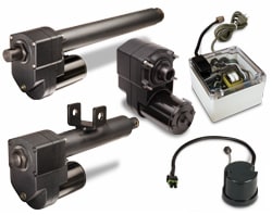
A wiring diagram is a simplified standard photographic representation of an electric circuit. Here s the diagram describing a process. Warner linear h track actuators. Warner linear electric actuators and controls.
Warner linear h track actuators. Warner linear h track actuators. Warner electric linear actuators. Warner linear electric actuators and controls.
Connect the negative terminal of the power supply to the t3. By admin march 13 2018. Follow the instructions described in the linear actuator wire diagram. Our linear product line offers linear actuators and controls.
Linear actuators are ideally suited for intermittent duty cycle applications requiring lift lower push pull positioning sorting opening or adjusting on both in plant or mobile applications. Assortment of warner linear actuator wiring diagram. Warner electric engineers utilize the latest materials and manufacturing technologies to design long life easy to use clutches and brakes that provide improved accuracy and repeatability. Other major product lines include tension brakes and controls available from a single manufacturer along with sensors and.
Connect terminals number 3 and 4.

Yx 4003 Wiring Diagram Auma Motorised Valve Wiring Diagram Motorised Valve Schematic Wiring
Abz Electric Actuator Wiring Diagram Linear Actuator Wiring Diagram Free Wiring Diagram Abz Pneumatic And Electric Actuators Valve Automation Limitorque L120 Wiring Diagram Collection Wiring Collection Warner Linear Actuator Wiring Diagram Free

External Limit Switch Kit For Actuators In 2020 Linear Actuator Actuator Switch

Diagram Borg Warner Actuator Wiring Diagram Full Version Hd Quality Wiring Diagram 1cabinetwiring1 Mairiedebonnat Fr

Zl 7420 Borg Warner Gauge Wiring Diagram Wiring Diagram

Stewart Warner Stewart Warner 3 3 8 In Wings Electric Diesel Tachometer 3 500 Rpm 82672 82672

Synchronous Control Of Two Optical Linear Actuators Using An Arduino Linear Actuator Arduino Actuator

How To Adjust Limit Switches On Heavy Duty Linear Actuator Progressive Automations Youtube

External Limit Switch Kit For Actuators Linear Actuator Actuator Switches

Gx 7338 Van De Graaff Generator Diagram Http Wwwpic2flycom Vandegraaff Free Diagram

Single Phase Wiring Diagram For House Bookingritzcarlton Info Electrical Circuit Diagram Circuit Diagram Capacitors

Diagram Time Warner Wiring Diagrams Full Version Hd Quality Wiring Diagrams Humanbraindiagrams Blidetoine Fr

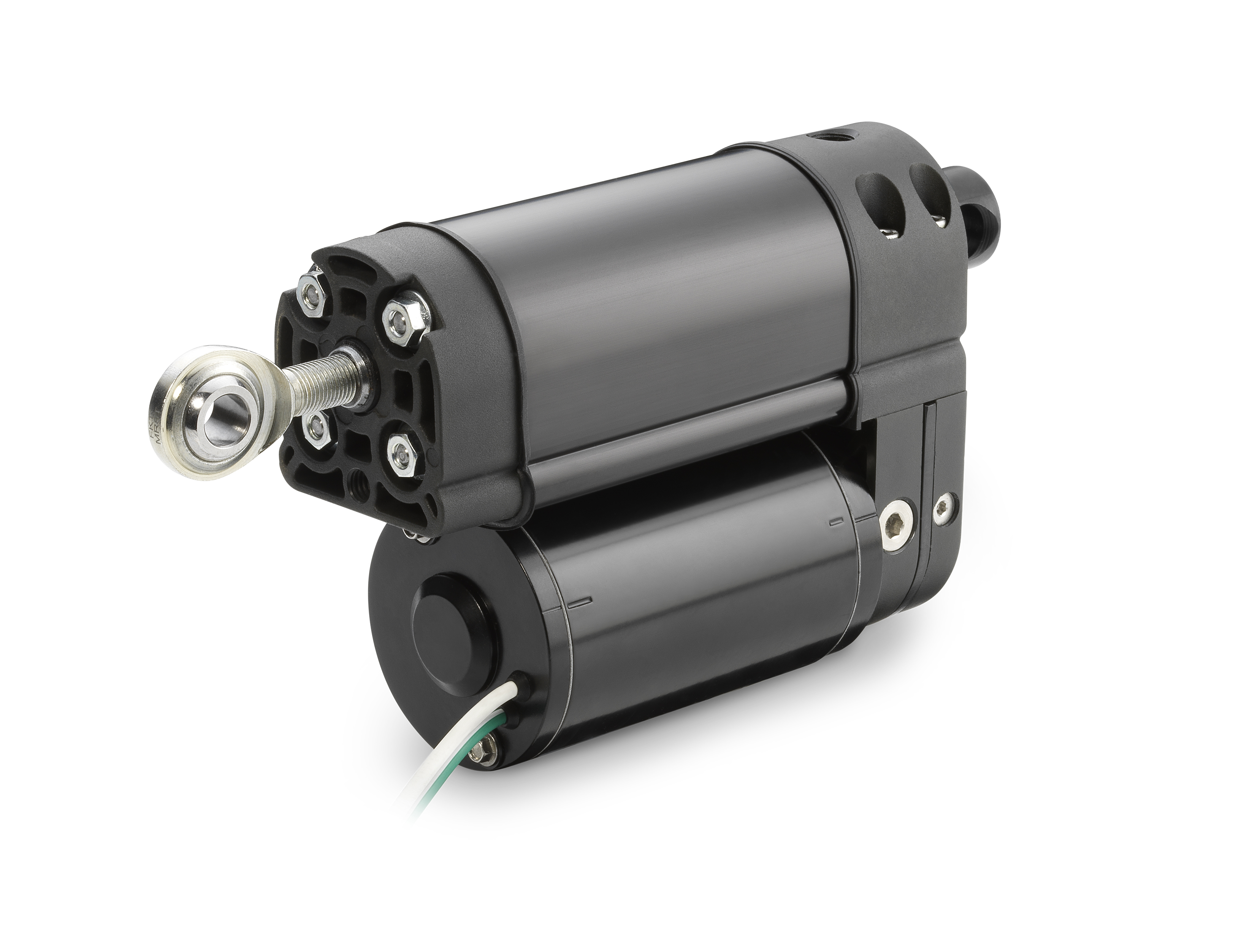
Warner Linear H Track Electric Actuator Youtube

Warner Electric Linear Actuator P N S12 17a8 06 25320 Flying Fish Aircraft Parts

Diy Reciprocating Cycle Linear Actuator Motor Electric Motor Gear Box 24v 200rpm Ebay
How To Wire A Linear Actuator To 3 Way Toggle Switch Youtube
Linear Actuators Thomsonlinear Com
Https Www Thomsonlinear Com Downloads Actuators Warner Electric Actuators Controls Cten Pdf
Https Encrypted Tbn0 Gstatic Com Images Q Tbn 3aand9gcqynvk5pvrcfr 2vswjrmkhmb8 Icnxzinzshs Arpwhx9hd0q8 Usqp Cau

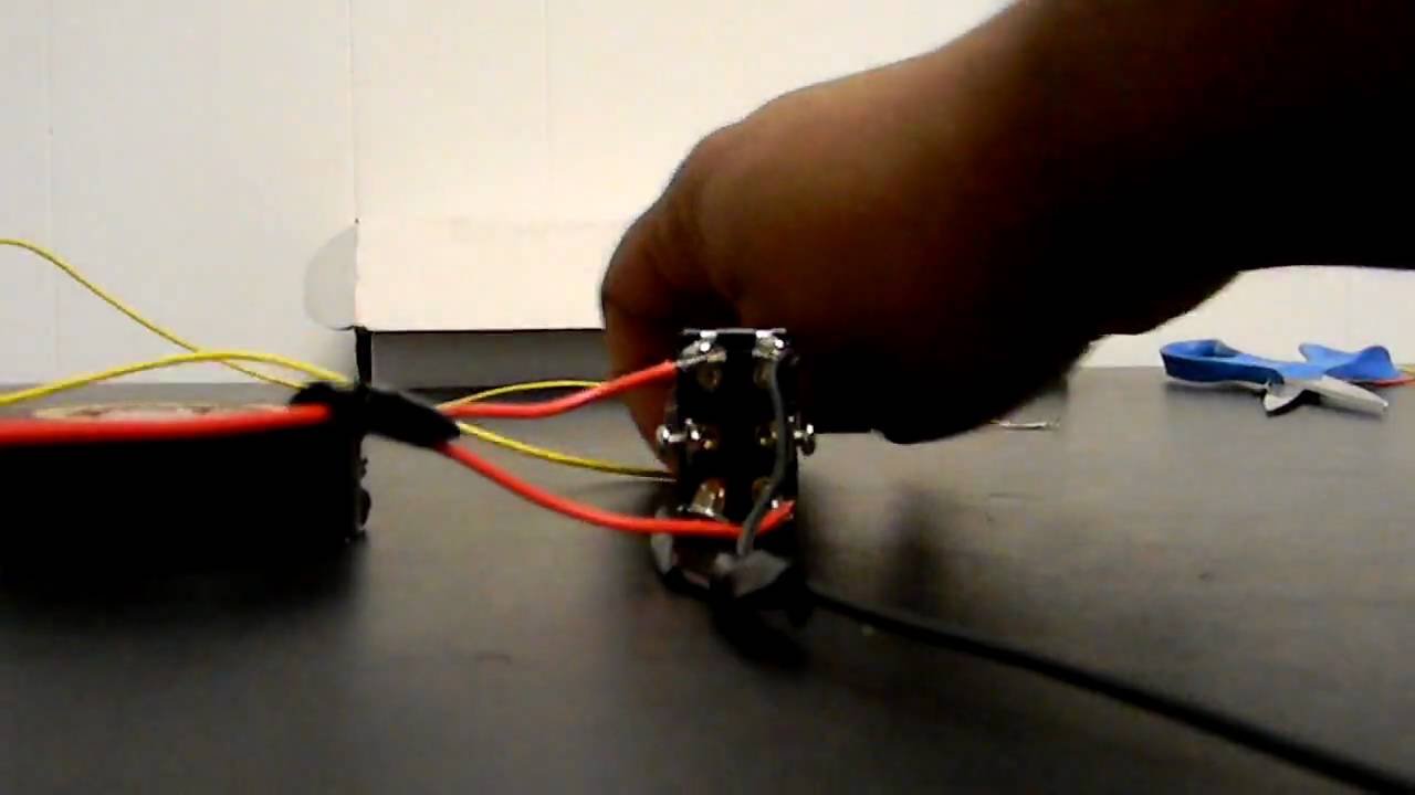
Wiring Limit Switches On A Linear Actuator Instructables
Warner Electric Power Transmission Products
Actuator Wire Diagram Wiring Diagram For Linear Actuator Switch Wiring For Linear Actuator Electric Camber Tilt Linear Actuator Wiring Diagram Free Wiring Diagram Linear Actuator Wiring Rcs Actuator Wiring Diagram Collection External

Linear Actuator Applications Google Search Linear Actuator Actuator Mechanical Gears

Linear And Rotary Actuators Motorized Linear Slides Cylinders And Actuators Linear Actuator Linear Actuator

Borg Warner 44 06 Transfer Case Transfer Case Borg Repair
Ppt Auma Electric Actuators Powerpoint Presentation Free Download Id 2734345
Linear Actuators 2 Linear Actuator

Push Button Control With Arduino Arduino Control Linear Actuator

12 Complex Electric Motor Wiring Diagram Ideas Https Bacamajalah Com 12 Complex Electric Motor Wiring Diagram Ideas Diagram Diagram Chart Diagram Wire
Cummins Marine Diesel Engine Wiring Diagrams Seaboard Marine

Potentiometer Feedback Linear Actuator With Arduino In 2020 Linear Actuator Arduino Arduino Motor

Warner Electric Linear Actuators Warner Electric Parts

V7 Engine Diagram Pdf Di 2020

Linear Solenoid Actuator Theory And Tutorial Electronics Components Actuator Electrical Connection

Linear Solenoid Actuator Theory And Tutorial Electronics Education Electronic Schematics Circuit Diagram

Linear Actuators Firgelli Automations Of America In 2020 Linear Actuator Actuator Linear

Linear Actuators 101 How Does An Actuator Work

Z8 Engine Diagram Jakarta Di 2020

How Does An Electric Linear Actuator Work

Controlling Multiple Linear Actuators From A Single Controller Youtube

Distributed Control System Architecture For Profibus Field Instruments Distributed Control System Foundation Programmable Logic Controllers

Warner Linear How To Adjust The Limit Switches For A K2 Or K2x Actuator W External Limit Switches Youtube

How To Wire A Dpdt Rocker Switch For Reversing Polarity Reverse Switch Rocker

